

Image by Fæ, via Wikimedia Commons.
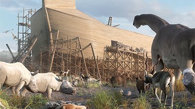
Could Animal Power Have Helped Noah Build the Ark?
Draft Animals and Noah’s Ark
Draft Animal Power (DAP)
Ancient people were more intelligent than modern people typically allow. The technology of Noah’s day included the ability to leverage the basic laws of physics to move and cut large timbers and stone, use various metals in different applications, and make pottery that could have been used for various lighting and storage purposes, as explained in “What Technology Was Available to Build the Ark?” An aspect not explored in that article is the possible use of domesticated animals for various types of labor.
Were Draft Animals in Use Pre-Flood?
Genesis 4 tells us that Abel was a shepherd, which indicates at least some level of animal domestication pre-flood. While we are not told specifically which animals were domesticated, we know that modern varieties of draft animals are the product of human selection post-flood. However, it is possible that at least some varieties of animals existed that were domesticated enough to be suitable for some of the uses below, and the use of draft animal power is attested to in the earliest civilizations post-flood.
Possible Uses for Draft Animal Power
When an animal is used to pull a load, it is termed Draft Animal Power. One would expect Noah to have made deliberate use of DAP during the construction and voyage of the ark. Typical applications could include:
One would expect Noah to have made deliberate use of DAP during the construction and voyage of the ark.
- Refining foods—e.g., milling flour
- Sawing timber
- Lifting construction loads
- Cartage of timber and supplies
- Plowing and farming
- Pug mill for pottery preparation
- Bellows operation for metal casting furnace
- On board the ark—pumping, lifting winch, cartage, etc.
How Much Power?
The working speed for most draft animals is about 1 meter/second (3.6 km/h, 2 mph). A Brahman bull consumes about 3.3 Joules for each Joule of work. There are limitations on the performance of animals, such as sensitivity to food supply, getting sick, wearing down from overuse, or just having a bad day.
| Sustainable power of individual animals in good condition1 | |||||||
|---|---|---|---|---|---|---|---|
| Animal | Typical weight kN (kgf) | Pull-weight ratio | Typical pull N (kgf) | Typical working speed m/s | Power output W | Working hours per day | Energy output per day MJ |
| Ox | 4.5 (450) | 0.11 | 500 (50) | 0.9 | 450 | 6 | 10 |
| Buffalo | 5.5 (50) | 0.12 | 650 (65) | 0.8 | 520 | 5 | 9.5 |
| Horse | 4.0 (400) | 0.13 | 500 (50) | 1.0 | 500 | 10 | 18 |
| Donkey | 1.5 (150) | 0.13 | 200 (20) | 1.0 | 200 | 4 | 3 |
| Mule | 3.0 (300) | 0.13 | 400 (40) | 1.0 | 400 | 6 | 8.5 |
| Camel | 5.0 (500) | 0.13 | 650 (65) | 1.0 | 650 | 6 | 14 |
| Note: For animals of different weight, the power output and energy output per day may be adjusted proportionately. Source: Tools for Agriculture, 1992 | |||||||
| Sustainable power of individual animals in good condition2 | |||||||
|---|---|---|---|---|---|---|---|
| Animal | Force Exerted (lbs.) | Velocity (ft./sec.) | Power (ft-lbs./sec.) | Standard Horsepower | Force Exerted (N.) | Velocity (m/s) | Power (W) |
| Draft horse | 120 | 3.6 | 432 | 0.864 | 535 | 1.1 | 587 |
| Ox | 120 | 2.4 | 288 | 0.576 | 535 | 0.7 | 391 |
| Mule | 60 | 3.6 | 216 | 0.432 | 267 | 1.1 | 293 |
| Donkey | 30 | 3.6 | 108 | 0.216 | 134 | 1.1 | 147 |
| Man | 18 | 2.5 | 45 | 0.090 | 80 | 0.8 | 61 |
For a hard day’s work, the horse reigns supreme, delivering 500 W for 10 hours. The ox is known for its compliance and is less fussy about food—a good choice for the less demanding applications. The camel has the highest power output, while the donkey has the lowest.
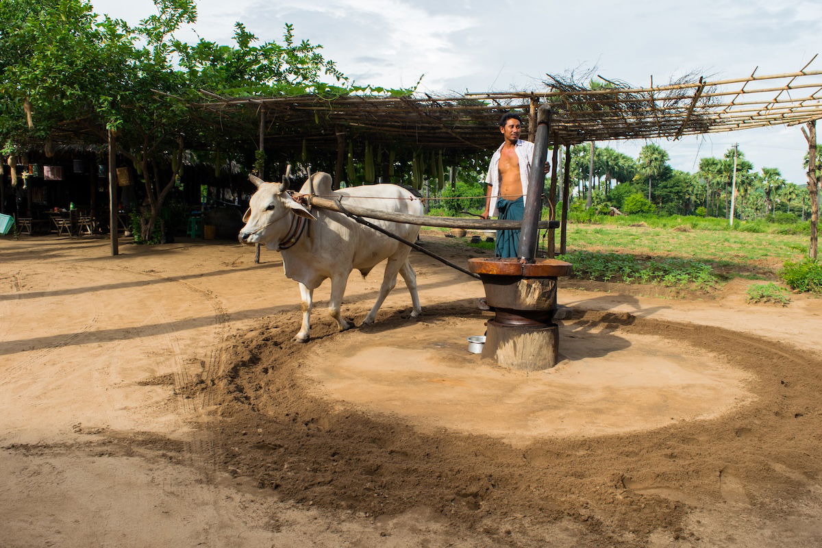
An ox crushes peanuts on a tiny mill in Thailand. Note the two arms—one steering the animal at the neck, while the other takes the power from behind the animal. Image credit: Getty images
Animal Driven Saw
A saw requires suitable steel—hard but not brittle. Forging (hammering) the metal is better than casting, which is too brittle. Hand sawing required two men—the tillerman on top of the log who lifted the saw and the pitman underneath who pulled on the cutting downstroke. A sawyer team could cut around 200 lineal feet per day (10 hours), but this is no doubt on a good day.
James Watt (1736–1819), famous for steam engines and the unit of power, calculated the unit of horsepower from a similar arrangement used in English mines. The horses trod a 24-foot diameter circuit some 144 times per hour, pulling around 180 lbs. While a bit optimistic for a full day’s output, this figure became the definition of the horsepower (hp) still used today (another nice example of long-lived units of measure).
The Up-and-Down Saw
To mill timber, a reciprocating saw has the simplest blade, a potentially excellent cut, and low power consumption (as compared to the better-known circular saw or the rather “high-tech” band saw). For example, a reciprocating 48" gang saw might have 25 to 50 blades and require 225 hp, the same power as an 8 ft. band saw. Of course, the band saw cuts very fast.3
The image below is of a water-driven reciprocating saw. Note the timber frame (sash) holding the saw blade. It wasn’t rare before steam and electricity. With this arrangement, which included an indexing system to move the log on the downstroke, a week’s work for two men could be done by one man in a day (14 times faster than hand (pit) rip-sawing and far more accurate).
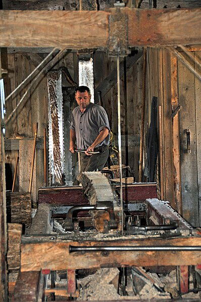
Reconstruction of a water-powered, up-and-down sawmill. Image credit: Dennis G. Jarvis, CC BY-SA 2.0 , via Wikimedia Commons
One difficulty with animal power on a saw like this is the load fluctuation. The animals would be stressed by the constant pulsing of force on the downstroke of the saw. This is offset to a degree by the weight of the saw frame (sash) and can also be minimized by the use of a timber flywheel. With the animals taking a full 25 seconds for one revolution, the saw would need to be geared up using a rope drive. An output power of nearly 2 kW (2.7 hp) could be achieved using four horses, which, driving a narrow blade, could give a domestic chain saw a run for its money. (The wider cut of a chain saw requires proportionally more power).
Layout
Power transmission from the animal turn-style to the saw crank could be achieved using a rope drive. The following illustration is from the 1964 edition of Kent’s Mechanical Engineer’s Handbook, which included a chapter on rope drives despite them being made obsolete by the introduction of electric motors. In the continuous rope drive, a single loop of rope makes multiple passes in grooved sheaves. In Noah’s case, these could be timber. A tension sheave is essential to maintain adequate tension as the rope stretches with use.
Kent’s Mechanical Engineer’s Handbook, 12 ed., 1964.
A section view of a tentative sawmill layout, using four horses and rope drive to an up-and-down saw.
To provide a higher gear ratio, a large drive wheel must be utilized to keep the driven sheave from becoming too small. The plan below shows a horse-driven flour mill in Vámosoroszi, Hungary, built around 1840. The horses walk on the inside of a 12 m gear—this diagram shows three horses and a seated attendant going along for the ride. The driving wheel has 370 cogs, which mesh with approximately 12 cogs on the mill, giving a gear ratio of around 30:1. Interestingly, this mill operated until 1948.
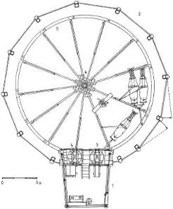
Image credit: Kaboldy, via Wikimedia Commons
Applying this concept, the 12 m diameter drive wheel now gives the saw a higher cycle rate, which reduces the speed fluctuation. A modest timber flywheel will do the trick here. The other trick is to sufficiently weigh the sash frame to aid the downstroke and collect potential energy during the raise, which means the unit would run unevenly when not under load. This could be tweaked using counterweights on the flywheel.
Proposed DAP Reciprocating Saw. Refer to DAP Saw Calculations below. This saw has a stroke of around 1 m, limiting the log diameter to this figure to allow saw teeth to clear. Lumber larger than 1 m poses a mass problem anyway and would need to be prepared by hand-sawing to a smaller section. The main purpose of this saw would be the production of accurate planking. Of course, Noah could always make a bigger one, assuming he could get wheels to move logs of 10 or more tons.
Log Motion
Villards up-and-down sawmill of the thirteenth century
Villard de Honnecourt’s manuscript (circa 1220s or 1230s) illustrates an up-and-down sawmill and a method of moving the timber forward. He included this note in his sketchbook: “How to make a saw operate itself.” While he could have used some lessons in perspective drawing, this is a long time before the “industrial revolution” but shows the essentials of an automated timber mill.
In the typical water-driven up-and-down saw of the 1800s, a ratchet mechanism advanced the log during the downstroke some 1/4" to 5/8". The early wooden frame design (sash frame or English Gate) provided speeds of 160 to 220 strokes per minute, cutting around 500 ft. of timber per day. There was also a system for sideways movement of the log to set the board thickness. All this moved on a system of timber rails or skids that were later replaced with steel.
In the proposed design, the log carriage is not shown. For an oversized mill, wheel bearings are a problem with heavy loads so rollers could be used to take the weight force with timber guides for lateral stability. For a standard-sized log, a simple skidding action would suffice.
Comments
Of course, it all seems rather speculative once the details are fleshed out. If Noah were to use labor-saving devices, wood processing would be the first candidate, and animal- or water-driven saws the best contenders. Water drive is superior in terms of minimal labor, but the technology looks too “modern” and familiar, despite the use of Roman waterwheels for driving flour mills. As for speculation, there is no choice in a detailed 3D scene—something must be specified. Our rules are simple—no heat engines or precision machine tools, but ample resources and ingenuity.
If Noah were to use labor-saving devices, wood processing would be the first candidate, and animal- or water-driven saws the best contenders.
A Word About Dinosaur Power
While a clear reading of Genesis 6–8 mandates that dinosaurs were on the ark (as air-breathing, land-dwelling creatures), the proliferation of dragon legends provides additional evidence that dinosaurs survived on the ark; however, it is unlikely these “reptiles” would be much use for DAP. Although it is not known exactly how intelligent a dinosaur was, if they were anything like modern reptiles, then it is no candidate for a beast of burden. This idea may work well for fictional shows like The Flintstones and Dinotopia, but our ability to harness their power for labor is likely another story.
We should exercise caution when describing what animals Noah would have or could have used for labor because we are looking at modern animals and making assumptions about their antediluvian ancestors whose size and temperament may not have been the same. If we can safely assume that the following kinds are quite similar to their pre-flood counterparts in ability and temperament, then perhaps a creature like an elephant could have been used for brute force, a member of the cattle kind for moderate effort, and a member of the horse kind for maximum daily output. Perhaps a job for dino-power could be dragging oversized logs through the forest, led by a mouth-watering selection of its favorite fruits. Then again, a hundred oxen might be easier to handle than one of these beasts.
WATT’S HORSEPOWER CALCULATION
The horse traveled 144 / 60 = 180.96 feet per minute.
Energy = force x distance, so the horse output was 180.96 x 180 lb. = 32,580 ft.-lbs. every minute.
Power = energy / time, so the rounding off, Watt calculated the horsepower = 33,000 ft.-lbs./min.
Of course, as an Australian, I believe everything is much easier in metric.
The horse covers 22.98 m every 144 / 3,600 = 25 seconds, which is a speed of 0.919 m/s.
Power = force x velocity = 800.7 x 0.919 = 736 Watts.
(The rounded figure gives the standard conversion; 1 hp = 745.7 W)
CALCULATIONS FOR PROPOSED DAP SAW: (metric) Ref Kent’s Mechanical Engineer’s Handbook 12 ed.
ASSUMPTIONS
Horse speed = 1 m/s; diameter of horse path = 9 m; number of horses = 4; diameter of drive wheel = 12 m.
Ang Velocity of drive wheel: W1 = V / R = 1 / 4.5 = 0.222 rad/s (2.12 RPM)
CHECK ROPE TENSION
Assuming each horse supplies 500 W; total power = 2 kW, so torque is 2,000 / 0.222 = 9,000 Nm
Therefore tension is F = T * r = 9,000 / 6 = 1,500 N (336 lb.)
Since pretension must be 50%, the rope tension is doubled; Tmax = 3,000 N (673 lb.)
(Working load for 9/16" or 14.3 mm, manila rope is 690 lb.)
DRIVEN SHEAVE DIAMETER
Check arc of contact on small pulley; T1 / T2 = exp (fcoeff * arcofcontact)
Assume coeff of friction = 0.25 (Manila rope on wood—very conservative)
Then Arc of Contact = 2.77 rads = 158 degs. This is easily achieved, our design is well over 180 degs.
So select driven diameter based on 40 times rule: Diam = 40 * 14.3 = 571 mm. (Kent’s 15–82)
(Using two cords at smaller diameters would allow a smaller driven sheave).
We will assume a generous 750 mm driven pulley.
SASH WEIGHT
Velocity ratio VR = D1 / D2 = 12 / 0.75 = 16
Ang Vel of driven sheave = W1 * VR = 0.222 * 16 = 3.556 rad/s (33.95 RPM, or 1.767 secs/cycle)
Assuming two horses (1,000 W) can lift the sash, Work = Power * time = 1,000 * 1.767 / 2 = 883 J
Equating to PE = mgh --> m = PE / gh = 883 / (9.8 * 0.56 *2) = 80 kg (light but OK).
This gives the upper limit for sash weight at this RPM. It appears we cannot go any faster without an extra lightweight sash.
Assuming the log advances at 0.4" per stroke, this saw would cut at close to 1 ft./min., or 60 ft./hr.
FLYWHEEL
Now do energy balance on the saw upstroke; (KE of flywheel, PE of sash, work of horses, no cutting on upstroke.)
PE1 + KE1 + Work = PE2 + KE2
Take PE1 = 0, then PE2 = 883 J from above.
Work = Power * time = 2,000 * 1.767 / 2 = 1767 J
Now, assume allowable speed fluctuation of 10%; which means kinetic energy varies 21% (velocity squared)
KE1 + W = 1.21 * KE1 + PE2
So KE2 = ( W − PE2 ) / 0.21 = 4,207 J
Need a flywheel to store this energy at 3.556 rad/s;
Energy = 0.5 * Inertia * angvel ^ 2
Inertia = 665.6 kgm2
Assuming a timber disc 0.3 m thick and a density 600 kg/m2 gives a disc radius of 1.24 m. (diameter 2.5m)
So did Noah have to do these calculations? Not likely. Engineers usually do calculations, so they don’t have to arrive at a design by trial and error (or at least get there quicker anyway). In this design, the Sash geometry is common sense, and the drive wheel diameter is dictated by the size of a horse, leaving the diameter of the driven sheave as the only real variable to play with. The flywheel is optional and could be an afterthought.
Editor’s note: This article is based on content that was originally published at WorldwideFlood.com.

.jpg)
Footnotes
- FAO, Environment and Natural Resources Working Paper No. 4, Chapter 2: Energy for Agriculture (Rome, 2000), https://www.fao.org/4/x8054e/x8054e05.htm.
- Thayer Watkins, “Comparison of Power Produced by Various Draft Animals and Humans,” Applet-magic, http://www2.sjsu.edu/faculty/watkins/animalpower.htm. Metric conversion by Tim Lovett.
- R. T. Kent, Kent’s Mechanical Engineer’s Handbook, 12 ed., (Hoboken, NJ: John Wiley & Sons, 1964).
Support the creation/gospel message by donating or getting involved!

Answers in Genesis is an apologetics ministry, dedicated to helping Christians defend their faith and proclaim the good news of Jesus Christ.
- Customer Service 800.778.3390
- Available Monday–Friday | 9 AM–5 PM ET
- © 2026 Answers in Genesis